Construction layout translates digital design intent into precise physical markings in the field, converting drawings and models into accurate points, lines, and references on the slab. This process is critical, as any inaccuracy at the layout stage can cascade into rework, delays, and downstream quality issues. Traditional manual layout methods often take weeks or even months to complete and typically require crews of two to eight workers to execute.
Automated robotic layout compresses this timeline dramatically, completing the same scope of work in hours rather than weeks. Robotic systems also deliver materially higher accuracy and repeatability by eliminating manual measurement errors and fatigue. In this article, we explore why construction layout is foundational to project success and examine how robotic automation is transforming the layout process, from its practical advantages to its ongoing evolution on modern jobsites.
What is Construction Layout and Why is it Important?
One of the most critical tasks on any project, construction layout is the process of transferring drawings and digital models into the physical space on site. Core building elements such as framing, exterior lines, columns, walls, and utility runs are marked to ensure each component is placed in the correct location. Exterior layout commonly relies on stakes, flags, and fixed reference markers, while interior layout uses chalk lines, ink markings, and point references to define precise positions, boundaries, and control lines within the structure.
Accurate building layout is essential for coordination across multiple trade disciplines. Each trade depends on reliable layout data and must align its work with adjacent scopes to avoid conflicts. Drywall layout, for example, defines wall locations, door openings, curved walls, soffits, and finish types. MEP layout identifies hanger locations, ductwork and piping runs, equipment placement, and electrical device locations. Façade layout establishes panel centerlines, offsets, and setbacks to ensure proper weather sealing and a consistent visual appearance. Project layout may also include building footprints, structural elements, and dimensional controls required for prefabricated assemblies.
Project success in construction is often directly tied to layout accuracy. Errors at the layout stage can lead to rework, increased labor and material costs, and significant schedule delays. When one trade introduces a layout error, the impact frequently cascades to downstream trades, compounding both cost and time impacts. Precise layout ensures the structure aligns with design intent and provides a clear, reliable guide for every trade to execute its work correctly the first time.
Despite its importance, most construction layout is still performed manually by skilled workers. This work requires repetitive bending, kneeling, and sustained physical effort, which increases the risk of injury and long term musculoskeletal strain over the course of a project.
Manual Layout vs. Robotic Layout
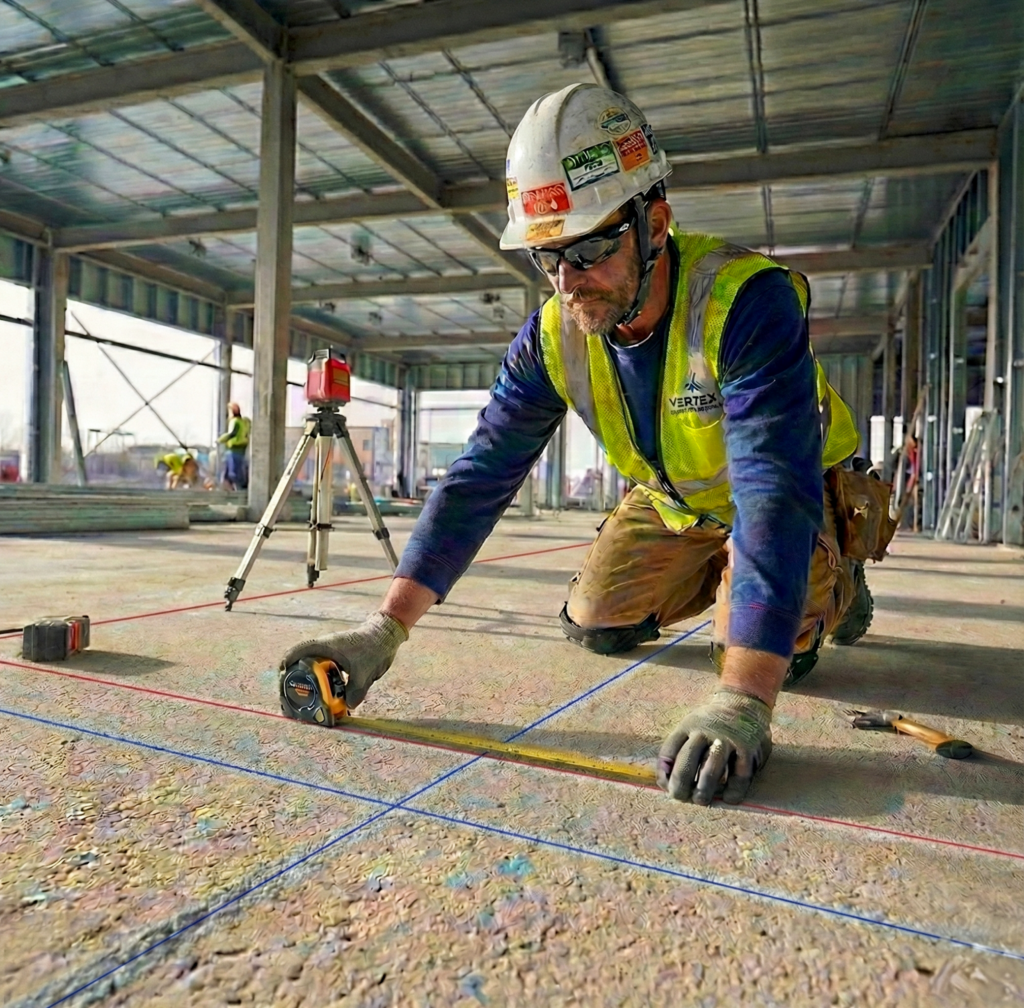
Manual layout, where skilled workers measure and mark building locations by hand, involves a series of time intensive and sequential tasks. These typically include clearing the work area of obstructions, reviewing architectural plans on paper or on a tablet, and localizing a total station to established control points or creating independent control from a shared project reference marker. Crews then upload layout points, often in CSV or similar formats, mark reference points in the field, snap chalk lines to connect those points, and back-check accuracy through resections. simple orthogonal geometries such as squares and rectangles, this workflow can appear relatively efficient.
Primary control lines and boundary conditions are often established using a total station to define the layout box. However, intermediate elements within that box, such as anchor locations, mullion centerlines, embeds, or other high repetition, constant spaced features, are frequently filled in using tape measures taken off the bounding lines. This practice introduces additional error through tolerance stackup, as small measurement deviations compound across repeated manual measurements.
Execution speed is driven by both the number of points required and the tolerance demanded by the scope of work. Straight framing layouts may require relatively few control points, while denser scopes increase marking effort and verification time.
Tolerance requirements vary significantly by trade. Framing may allow tolerances of plus or minus half an inch, while façade systems often require precision as tight as plus or minus one sixteenth of an inch. Tighter tolerances increase the need for backchecks, slow the marking process, require additional instrument setups, and significantly extend layout duration. For this reason, layout productivity is not directly comparable across trades.
Complex building geometries, intricate layout schematics, and high density marking often push manual layout well beyond what is assumed in schedules and estimates. These conditions strain both accuracy and productivity, increasing the likelihood of errors and downstream rework.
Manual layout is also susceptible to common execution issues. Drawings and digital models can be misinterpreted in the field, particularly when details, offsets, or reference conditions are unclear. Fatigue, time pressure, or complacency can lead to shortcuts such as marking fewer points than required, skipping backchecks, or relying on visual judgment instead of verified measurements. Environmental conditions further complicate accuracy, as temperature changes, slab movement, dust, moisture, and site congestion can shift reference conditions over the longer duration of a manual layout scope. In some cases, layout points are adjusted in the field to resolve perceived conflicts without clearly communicating those changes to other trades or updating the underlying model, creating misalignment across scopes.
Beyond measurement and interpretation, the physical marking process itself introduces additional error. Manual points are commonly marked using chalk, wax pencils, or similar tools that lack fine resolution and are prone to smearing, wear, and inconsistent line thickness. Workers then visually align and snap chalk lines between points to establish layout lines. This visual alignment introduces further variability, particularly over long runs or dense layouts, where small deviations accumulate into meaningful misalignment.
Construction layout robots address many of these challenges by integrating directly with digital building models and using autonomous machines to print layout markings onto the slab or ground. Robots maintain continuous communication with a total station, allowing seamless movement between points without repeated setup. This approach delivers faster execution, consistent accuracy, and significantly reduces physical strain on workers.
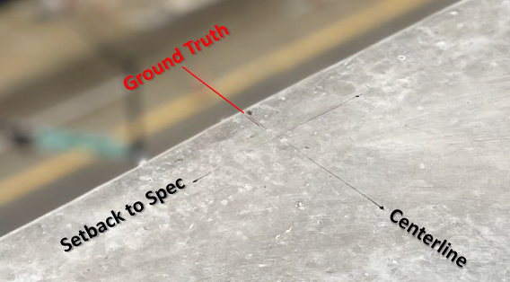
It is also important to recognize that both manual and robotic layout accuracy are fundamentally dependent on the quality of the control points provided on site, typically by the general contractor. These control points establish the reference framework for all downstream layout activities, and their required accuracy is defined in the project contract documents. On many projects, control points are specified at plus or minus one eighth of an inch. While this may be sufficient for lower tolerance scopes, tighter control is often required to fully realize the benefits of automated layout. For best results, control accuracy of plus or minus one sixteenth of an inch should be specified, particularly for façade, MEP, and other precision driven trades.
The accuracy of the control network is the first and most limiting factor in determining layout performance. If the established control points have an accuracy and fit of plus or minus one eighth of an inch, it is not possible to achieve discrete layout point accuracy tighter than that threshold. Layout precision can only be as good as the control framework on which it is built, making early investment in a tight, well coordinated control network essential.
Assuming properly established and tightly controlled site control, construction layout robots have proven to be substantially more precise than manual methods. Robotic systems routinely achieve tolerances as tight as approximately 0.19 inches, or 2 to 3 millimeters, compared to 0.39 inches, or 5 to 10 millimeters for even the most experienced layout professionals. This higher level of accuracy translates directly into lower project costs and fewer schedule disruptions, as crews spend less time reworking installations or double checking layout and more time advancing core construction activities.
The table below summarizes the key differences between manual and robotic construction layout across accuracy, speed, and labor requirements providing a clear side by side comparison of each approach:
| Manual Layout | Robotic Layout | |
|---|---|---|
| Accuracy | 0.39” (5-10 mm) tolerance | 0.19” (2-3 mm) tolerance |
| Speed | Slower, can take days or weeks | Faster, can be completed in hours |
| Labor Needs | Requires multiple skilled workers and physical effort | Requires one operator and reduced injury risk |
| Errors | High potential for rework due to human error | Minimizes or eliminates rework with high accuracy |
Types of Layout Robots
Not all robotic layout systems are built the same. While many solutions on the market rely exclusively on Building Information Models to operate, others offer greater flexibility in the types of files they can accept and how easily they integrate into existing construction workflows.
Some robotic layout systems, such as those developed by Raise Robotics, can work directly with standard CAD files. This eliminates the need for BIM conversion and makes robotic layout accessible to a broader range of projects, including those that are not fully modeled in BIM. By supporting CAD based workflows, contractors can adopt robotic layout without changing their design process or investing in additional software, training, or coordination overhead.
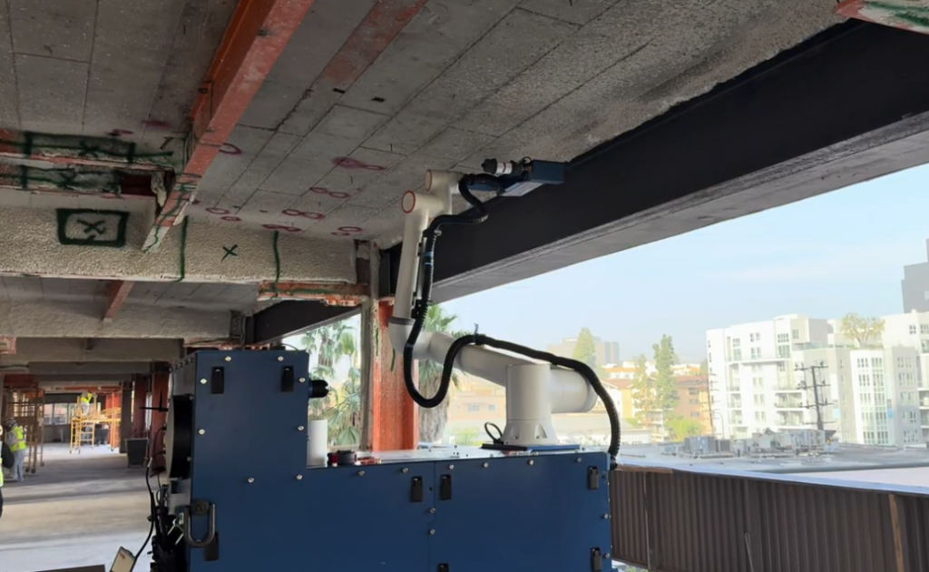
Marking capability is another key differentiator between layout robots. Many traditional systems are limited to marking points or lines on floors only. More advanced robotic layout systems can also mark ceilings and walls, expanding their usefulness across a wider set of trades and scopes. This capability is particularly valuable for MEP work, where overhead layout is common and precision is critical.
The ability to mark ceiling and wall points directly eliminates the need to manually transfer measurements from the floor to overhead conditions. This reduces tolerance stackup, shortens layout time, and lowers the risk of errors in hanger placement, penetrations, and equipment installs. As robotic layout technology continues to evolve, these expanded marking capabilities are becoming a key factor in determining which systems deliver the most value on complex, trade dense projects.
How Robotic Construction Layout Works
Robotic construction layout begins with preparing the same architectural or engineering design files used for manual layout. The total station is then set up and localized using established site control points, following standard field procedures. Instead of tracking a reflector or prism mounted on a bipod, the total station continuously tracks a prism mounted directly on a mobile robot, allowing the robot to know its position at all times. Using the same CSV point outputs generated for manual layout, the robot autonomously drives to each point of interest and marks the specified geometry at that exact location.
Preparing Digital Plans for Field Layout
Layout software uses CAD or BIM building models as the source of design intent. These files must include all required layout information, and any clashes or conflicts should be resolved prior to upload. Once finalized, the plans are uploaded to a cloud based platform where on site personnel connect the digital models to physical site locations using a tablet or smartphone. This step ensures that the digital coordinates align precisely with real world conditions before layout begins.
Localization & Site Setup
Control points are established using a total station or laser based surveying tools to define a reliable reference framework for the job site. During setup, the robot aligns itself to these control points and confirms its position and orientation before starting work. This process allows the robot to operate accurately across open slabs, tight interiors, or partially built environments without requiring extensive site preparation.
While operating, the robot continuously verifies its position using a combination of onboard sensors and external positioning data from the total station. This real time feedback enables small adjustments as site conditions change, helping maintain accuracy across long runs and varied environments. The result is a system that adapts to the job site, rather than forcing the job site to adapt to the robot, supporting consistent and repeatable performance as construction progresses.
Automated Point Marking & Verification
Once localized, the robot moves throughout the job site, marking precise points, lines, centerlines, text, and other specified geometries on floors, ceilings, and walls. Using onboard sensors, the robot detects obstacles, including workers and equipment, and dynamically adjusts its path without disrupting ongoing operations. Because the robot can complete layout for multiple trades in a single run, teams finish layout faster with fewer handoffs and reduced coordination overhead.
Data Capture & Reporting
Throughout the layout process, the robot continuously verifies its position and measurements to confirm that markings are placed exactly where intended. This built in verification maintains accuracy from start to finish and significantly reduces the risk of downstream errors, rework, and schedule impacts. As layout work is completed, the robot records progress directly from the job site, providing real time visibility into completed and pending scope without relying on manual updates. Potential issues can be identified early, before they escalate into rework or schedule impacts.
The same field data can be used to generate reports and as built documentation, creating a clear and reliable record of what was installed and where. This improves coordination between trades, simplifies quality control, and provides dependable documentation for project closeout and owner handoff.
The Benefits of Robotic Layout
Increased Accuracy and Precision
Robotic layout ensures walls, utilities, and other critical building elements are placed exactly where the design specifies. Continuous measurement verification throughout the layout process reduces errors and inconsistencies, improving overall quality and preventing misalignment issues that can slow construction progress.
Faster Layout and Improved Labor Efficiency
A single operator can manage a robotic layout system, replacing a traditional multi person layout crew. This significantly reduces labor requirements, accelerates layout timelines, and allows skilled workers to focus on higher value tasks elsewhere on the project.
Reduced Rework and Cost Savings
By delivering consistent, high precision markings, robotic layout minimizes layout related errors that lead to rework. Fewer corrections translate directly into lower labor and material costs, improved schedule reliability, and better budget control.
Improved Jobsite Safety
Robotic layout automates repetitive and physically demanding tasks, reducing the need for workers to kneel, bend, or work near edges, overhead conditions, or other hazardous areas. By limiting physical strain and exposure to risk, robotic layout contributes to a safer and more sustainable job site.
Improve Your Construction Layout Process with Raise Robotics
Raise Robotics delivers faster, safer, and more accurate construction layout on every job site, while also enabling localized execution directly at the point of work. By automating precise measurement, marking, and repetitive field tasks, Raise robots reduce errors, lower labor requirements, and keep crews out of hazardous conditions. In many applications, this localized capability removes the need for separate layout steps entirely, allowing operations such as drilling, anchoring, or installation to be performed directly from the same digital reference.
This approach takes construction automation a step further by closing the gap between layout and execution. Contractors benefit from fewer handoffs, reduced tolerance stackup, and tighter alignment between design intent and installed work. The result is more predictable schedules, improved cost control, and consistent, high quality outcomes across every phase of construction.
Discover how robotic layout and localized automation can save time, reduce rework, and improve project efficiency. Contact the Raise Robotics team today to learn how automated field execution can strengthen performance on your next project.